Monday, July 22, 2013

Fly that baby!

I thought I would take an aside and show you an experimental airplane project that is being built by one of our EAA members. Leo Drescher works every Saturday on the Aeronca Training Glider project. He bought a Fly Baby that he found in the local Penny Saver. The Fly Baber is a homebuilt, single-seat, open-cockpit, wood and fabric low-wing monoplane that was designed by the Boeing historian, Peter M. Bowers.

 
The Fly Baby. Its the plane in the middle :-)

The Fly Baby specs:

Model: 1A
Length: 18 feet 10 inches
Height (folded): 6 feet 11 inches
Wing span: 28 feet
Wing cord: 4 feet 6 inches
Empty weight: 605 pounds
Gross weight: 925 pounds
Fuel: 12-16 gallons
Power 65-85 hp
Cruising speed 110-115 mph
Rate of climb: 850-1100 fpm
Construction: wood and fabric
Airfoil: NACA 4412

Leo's Fly Baby, in his garage

Leo's plane looks quite different from the one in the first photo. You can see the many tools and parts that are required to build an airplane. Fortunately, one of the characteristics of an airplane builder is that he likes tools, and enjoys flipping through catalogues for ones he doesn't have but will probably need. And like most guy things, the best tools are always the loudest (A.K.A. air tools, etc).

This photo shows the fuselage on the right, upside down with the landing gear sticking up. To the left are the uncovered left and right wings. One wing is hanging from the ceiling on a pulley system so he can hoist it up to get it out of the way when not needed.

Because the construction is all wood, Leo's home airplane project complements the work he does on the Aeronca Training Glider. He brings to us an abundance of info, tips, and techniques which shortens our learning curve and speeds the project along.

Hopefully, in the fall when the temperature is cooler, Leo is going to have us over to see the project in person. 

By the Leo, have you named your plane yet? Gertrude, Louise, Marilyn (as in Monroe) . . . ?


Sunday, July 21, 2013

Is this a doodad or a widget?


Ha, gotcha. It's neither.

This cool little thing is a 'pitot tube', and it's part of the system used to measure airspeed.

The two tubes are connected to the altimeter by flexible hoses that connect to the right side of the device. At rest (no forward motion) the pressure in each tube/hose is equal. But, once the airplane starts moving the pressure in the upper tube is greater than the lower tube. This is because the upper tube has a hole in the front of it, but the bottom tube has holes in the side of it. The difference in air pressure causes the altimeter to accurately indicate the airspeed.

Why go to all this trouble? The problem is called a 'stall', which is when the airspeed over the wing is slow enough it looses lift and the airplane falls from the sky, typically resulting in a crash if close to the ground. So as they say, "Ya don't wanna stall, cause you gonna fall".

The close ups below show the insect protection device. I suppose you could call it an IPD, but I never heard anyone use that acronym :-)


IPD shown in the flying position, the wind hits the upper flap and lifts the cover from the opening in the front of the tube.


IPD in the resting position. Gravity pulls the cover down. 

Now, you might ask, "Why isn't there a similar device on the bottom tube? Because it has very small holes, so the bugs can't get inside.

Joe Miller bought this on the internet, and it will be refinished to look like new before attaching to the glider.

Sunday, February 24, 2013

Nice Fit

Final assembly: When all the parts are assembled.

Sounds logical. But . . .

Before parts are assembled for the "last time" there is lots to be done. Each part has to undergo a test fit because if the part doesn't fit, you really want to know before you glue and nail everything together.

Below, a rib and a couple of compression struts are in place and ready for inspection.


Sunday, February 17, 2013

Powder Coating - Part II

Paul powder coated these pieces.

It was tricky. There was a problem. It's called Faraday's Cage.


Faraday, a really smart scientist from long, long ago, found that electrical charges accumulate on the outside of an object, but not on the inside. These metal parts don't look like a cage, but because there are parallel surfaces, they act like a cage, and the electrical charge (and powder) doesn't stick to the inner sides of the parallel surfaces. The powder coating bounces off the inner walls and jumps to the outside surfaces.

How did Paul get it to stick?

Paul heated the parts before painting, then he held the gun close to the inner surfaces, and before the powder could jump to the outside they melted from the heat and stuck. 

They look good, don't they.


Sunday, February 10, 2013

You can't powder coat wood


Last week we looked at powder coating and the advantages. But can it be used on wood? Nope. Wood cannot conduct electricity, and it typically doesn't want to be heated to the temperature required for powder coating.

Ribs require a traditional varnish applied with brushes. It's a bit slow, since the varnish has to be applied into all the nooks and crannies of the rib, including inside the gussets. Somethings never change.


The new guy (Rishab) and Leo


Clarence had to help out; the young guys got tired and had to take a break :-)


Sunday, February 3, 2013

Powder Coating - Part I


Powder Coating 101

The piece of metal Paul is showing above has been powder coated (by Paul). It looks like it was spray painted, but there was no liquid applied, just powder.

How's that work?

Powder coating uses thermoset plastic (heat will melt it) mixed with coloring, and pulverized to a powder. It is usually sprayed on the metal parts with an electrostatic spray gun that applies a high voltage to the metal part, which attracts the plastic spray. As a result there is little, if any, overspray. Also, there are no runs, and no VOCs (volatile organic compounds) or smell.

Also, if you have never seen powder coating in action, it's really cool. The spray from the gun comes out like a regular spray gun, then it all magically redirects itself towards the part being coated, due to the magic of high voltage electricity. There is no (or very little) overspray. 

The part is then placed in an oven for a while, and voila, the plastic melts forming a nice surface that is tougher than paint.

In summary:

1. no smell or VOCs
2. thicker coatings with out drips or sags
3. overspray can be recycled.
4. less hazardous waste.
5. equiptment is low cost, if your wife lets you use her oven!


Paul ordered these samples to see which one matched the fuselage tubing on the glider.

Yup, you buy it by the pound, or in the case of this company, 1.2 pounds is the standard size


Paul laid the samples on the fuselage to see which one matched the best

Preeeeety close, what do you think?

Paul's been busy

Sunday, January 27, 2013

Leo's new toy

Remember Christmas morning? Waiting to unwrap those toys under the tree. It was magical, just think of the fun you were going to have with that new bicycle, model airplane, or science kit. Now it's different. Instead of cool toys, we get pajamas, or a tie. Makes you long for the good ol' days.

So, since our manly needs aren't being met by the packages under the tree, we have reverted to making our toys (sometimes). It's actually quite rewarding. We take a piece of scrap, a saw, and a vice, and voila, a cool new toy!

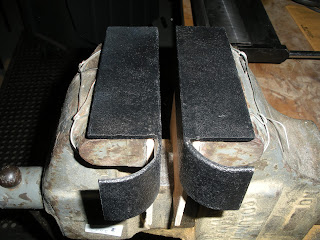
Leo needs a pipe flatner/bender (I am sure there is a more official name). The drawing below shows an example of what he needs it for. The pipe shown has to be attached at each end with a bolt, at a specific angle. So it must be flattened, bent, and drilled. Okay, drilling can be done with one of the six drill presses we have, but we don't have a flattener/bender thingy. 


This is one of those parts that is easy to draw, but hard to make (unless you have the right toy tool).


Leo saw this article written by Tony Bingelis, and her went to work.


The tool is simply a stout pair of angle iron, cut and bent to the shape shown, and inserted in a vice. This one is for symmetric flattening/bending.


 This one is for asymmetric flattening/bending.


And her is a little better photo from a different angle.

I thought it would be fun to wrap it up in a brightly colored package and put Leo's name on it. Hey, how long until April 1st?


Sunday, January 20, 2013

Tool Time

I thought it would be good to take a look around the glider project and see what kind of tools it takes to build an airplane:

Table saw

Radial arm saw, one of two.

Bench grinder and small sheet metal brake, for small quick jobs.

Large sheet metal brake with shear and slip roll, for larger or more complicated jobs.

Drill press, three of six, were rich! Why six? Because six were donated, and they can be used for so many things. Drilling holes, taping threads, sanding (with disks or drums). In fact, if multiple parts are needed, an assembly line can be set up with each drill press loaded with a different tool, then the parts can be drilled, sanded, etc; with out changing tools, simply by moving the piece from one drill press to the next!

Compound miter saw

12 inch x 6.9 inch planer, very good (fast) for reducing a thick board to a thin board.

Router with bench-top stand

Jig saw

Oscillating sander (concave curves) and disc sander (straight and convex curves)

Band saw. 
Mark, thanks for showing us how to tweek a plywood widget


Paul standing next to a turret sander. Turret sander? the thing his hand is setting on is the "turret". It is four sided and can be easily rotated to select any one of four different tools. Thus, multiple tools can be switched rapidly for parts that require many different operations. 

6 1/8 inch jointer/planer

Jointer/planer, close up view

Did you recognize any of the above tools? Maybe? Probably?

Think about this. If you are familiar with these tools, you can build an airplane! Maybe you are familiar with some of these tools, but not all. Never fear. Most of us are (or have been) in that same situation. We will never know EVERYTHING we need to know when we start a project. But, and I emphasize the BUT, if we have the desire, and some basic skills, we can develop the other skills needed to accomplish the tasks (yes, this applies to other things in life besides building airplanes). If you use any tools on a regular or semi-regular basis, then you have developed the necessary hand-to-eye coordination that will be used when learning how to use other tools. An old boss (Ken) once told me something that I have never forgotten.

"We don't wait to start a trip to New York City until all the traffic lights are green [that would never happen]. We start driving and when we come to the first red-light, we deal with it. The same with each red light we encounter. Eventually, we reach our destination"

Thank you, Ken.

So it is with any project. Don't be timid. Yes, we must plan, but we don't wait for all the lights to turn green.

If you live in the area, come and join us as we build an airplane, especially if you are considering building your own airplane. We have fun and fellowship, and learn about lots of interesting aviation stuff.


Sunday, January 13, 2013

Aileron Ribs

I like the following series of photos because it helps to understand the engineering process. First, you start with a design, in this case a drawing of an aileron rib.


Then you build it, but how? Do you take all of those measurements and put them on each rib? Heavens no. that would take forever, which BTW is a very long time, and we would like to speed things up a bit. So, Leo took the drawing and glued it to a piece of aviation plywood, then cut it out. Much faster, but if he did that for each one it would take a little less than forever


So, he used the first rib as a templete to make the others. Hmm, now you're talking speed. 

 This is rib number two, which looks a lot like rib number one except it doesn't have the paper drawing attached.


Reminds me of the story about rabbits, start with two, then . . . 


 Can you see the differences?


Look careful, see any other differences?

Occasionally the design requires some deviations. As we get farther along on the aileron assembly you will see why these differences are so important.


Sunday, January 6, 2013

Wassat?

Cool looking doodad . . .

Micarta sleeve bearing

This is a bearing for an aileron. It is a simple structure that provides rotation (sleeve bearing), and reinforcement for the tube that rotates inside. The micarta is attached somewhere on an aileron, and our best guess so far is shown below.


As the aileron is raised or lowered it turns on a tube that rotates inside the micarta.

BTW, what is micarta? It is cloth (linen, canvas, paper, fiberglass, carbon fiber, or other fabric) that is in a thermoset plastic. George Westinghouse started using phenolic resin as the thermoset plastic in 1910. So, it seems that this was the beginnings of what we now know as fiberglass.

So, now we have a new word. Wonder where we can use it? 

"Hey Honey, have you seen my high voltage micarta?"  

"They plates are flimsy, they should have made them out of micarta."

"Hey honey, when you are at the grocery store, could you pick up some half inch high pressure thermoset micarta?"

Yeah, we'll have lots of fun with this word. . . .

P.S. It is pronounced my-carta, not me-carta. I just noticed my voice synthesizer butchered it, ha.

Sunday, December 30, 2012

Christmas came early!

On December 15, 2012 I walked into the work area and found the following four guys looking at our new spars!!!!

We now have 4 spars, two front and two rear; enough to finish both the left and right wings, yippeeeee!

Joe found a cabinet maker that has a CNC machine, which drilled the holes with almost perfection. So, now it is a matter of putting the ribs, compression struts, wire bracing, ailerons, doodads, and flumdittys on the spars. It's going to get interesting; well, it has been interesting, but now it's going to get really interesting.


Left to right, Paul, Leo, Joe, and Rishab (aka the new guy).

Sunday, December 23, 2012

When it rains, it pours: New guys

Wow, three new people visited today (Dec 15, 2012)!

Below is a photo of John Schwarzkopf. John is taking on a project that was previously stalled. We have thousands (yes, thousands!) of model airplanes that we would like to sell. They have been put into a database and sorted. Then nothing, until John came along and volunteered to put them on ebay. He takes a couple at a time and takes photos, writes descriptions, posts ads, mails the models, and finally delivers MONEY to EAA 143. Cooool!

Who would've thought that ebay expertise would be so valuable to our glider project. The money that comes in is going toward our spar purchase, which is currently holding up our wing project. So, thank you John!


Two other visitors today:

John Kraft's grandson Gregg visited. Young blood--Fantastic! We need all ages, but right now we are heavily weighted towards the senior citizens. Moral of the story, if you are a young or old, or somewhere in between, come on out. Everyone is welcome.

Rishab Shyam also visited. Rishab just earned his private pilot license earlier this year, and now wants to learn about building airplanes because someday he may want to build his own. He flies a rental often, and will be in this area for another year or so while he finishes his PHD in biomedical engineering at John Hopkins.


Sunday, December 16, 2012

Compression Struts

What is a compression strut?

A compression strut fits between the front spar and rear spar (in each wing) and holds the spars the correct distance apart. They are in "compression mode" which means the spars are pulled together by criss crossed wires under lots of tension. So the only force the compression struts provide is, duh, compression. The wires also provide the force needed to keep the struts from moving laterally, more on this later when I can take some photos of the completed wing.

Two of the compression struts


Mechanical drawing of the compression strut, at one end.

The two pieces that will form one end of the compression strut, as seen in the mechanical drawing.

Note: the sheet metal was cut, deburred, and bent by Paul Straney. He had to tweek it very carefully because the fit has to be close to perfect in order for the welding process to work. Both pieces are thin metal, and there is little room for error when welding.


Sunday, July 15, 2012

OOPS!

This rib had a small defect. Look at the gusset at the top center.

The gusset was not pushed all the way to the edge of the rib, and so it did not provide all the necessary strength. Part of the gusset has been removed by Leo. He will remove the rest with sandpaper.

After sanding he spread epoxy and placed the new gusset in position.

Bing, bam, Done.

Time for Lunch while the glue dries. The subs were made fresh on the spot by Joe. He usually makes an extra one, so stop by and join us.